In this article, we’ll be discussing a Crank Drive with Periodic Change of Effective Level Length by Schmidt, US publication 20210163095. The publication date is June 3rd, 2021 and the filing date is July 18th, 2019. This patent has not been granted, yet.
This will be a short article because I’m just going to focus more on the physics of this idea, rather than the idea itself.
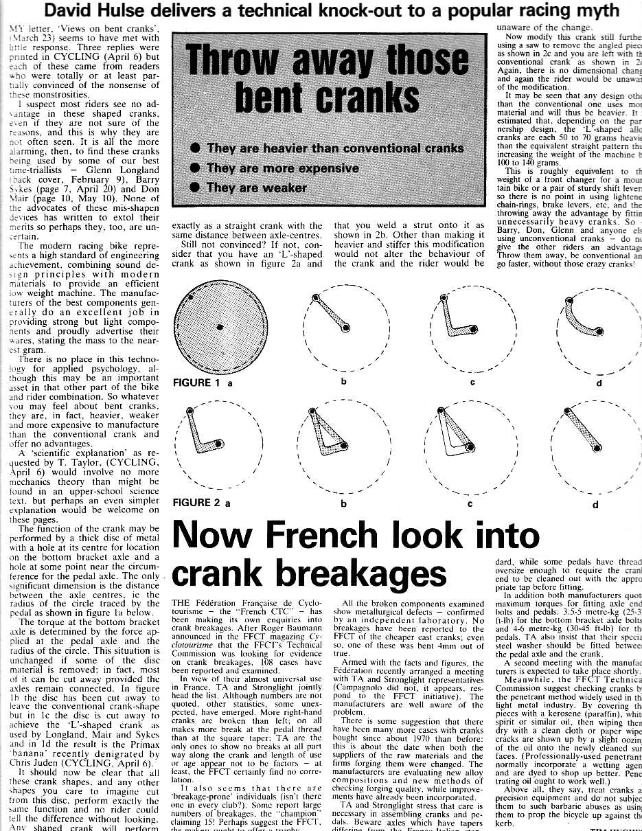
The design being presented here relates to the forces applied to a crank. The image below shows a typical pedaling cycle. When your pedals are at their highest and lowest positions (perpendicular to the ground), you experience what is called a ‘dead-center’. This refers to the inability to apply a rotating force to the cranks when you push straight down. As a result, there is zero resultant forces moving the bike forward. Therefore, the torque you apply to the cranks is lowest at the top and bottom positions of the cranks. Of course, a real-world scenario will obviously keep you moving forward, but this is because you’re pushing the cranks forward to compensate for the dead-center.

What this guy is doing is attempting to increase the power resulting from the cranks at the already-highest-force location of rotation, which will be at 90° from vertical, by variably increasing the lever arm length. The image above shows the locations of maximum and minimum applied forces to the cranks from your feet. So, what if we can increase torque at the 90° locations without explicitly lengthening the cranks or increasing the applied forces?
In the case of this design, the inventor says ‘conventional dead point zones are to be largely avoided’. Maybe he’s right, I’m not sure. But, there are a shit load of other concepts that try to resolve that, and none of them will work (unless you’ve got a motor). No, angled cranks don’t do shit. David Hulse wrote a piece all the way back in ’85 about this. If they worked, they’d probably be on our bikes by now.
FIG. 3, below, shows the system we’re talking about here. The crank arm has two major components, a typical crank arm, and a rotating extension. The rotating extension is fixed to the crank arm using a set of gears. As the crank rotates, the extension also rotates. As a result, the length of the lever arm increases at the peak-applied force location. Another bonus is that we don’t give up too much ground clearance as the extension continues to rotate.

So, why will this work? Let’s ignore the design itself and just talk physics. The equation for torque is:

With this idea, we’re variably increasing the r value (radius). Maximum torque is produced when the force acting on the crank arm is at 90°, and this is shown in the red box, above. Force is noted by F.
In the example scenario below, X is the typical distance from the crank center to the center of a pedal. This would be any normal crank design. X’ is the additional length of the rotating piece, and Y is the crank length plus the length of the rotating extension.

Now, let’s do some hypothetical calculations. Let’s use a X=170cm crank and 100 Newtons of force applied at 90°. With a typical system that we all use, the resulting max torque is 170Nm. Now, lets add the X’=20 cm at the maximum-torque location (90°) to create a Y=190cm crank arm. This will result in 190Nm of max torque by applying the exact same 100 Newtons of force, just by increasing the lever arm distance.
If you’ve ever worked on a car and couldn’t get a rusted bolt off your piece of shit truck, you probably went and reached for a longer wrench, or even a breaker bar. This is because as the lever arm length increases and the applied force stays the same, the resultant torque increases. You’re not applying any more force because you’re weak
Please note, I have no idea if these numbers are accurate to the real-world, I just used round numbers as an example.
As far as the design goes, the crank uses a set of gears to rotate the crank arm extension as the cranks are rotated. The shorter distance at the back of the rotation is only a result of the extension on the other end of the stroke and shouldn’t actually do anything, especially if you’re using flats.

Yes, I know, the gears could break. There’s extra complexity. Is this really necessary? Etc. This is just a physics lesson. There are obvious issues, but the math makes sense.
This same physics can be applied to brake rotor diameter. Don’t let anyone tell you bigger brakes aren’t better. “bUt tHe MoDuLaTiOn Is WoRsE”. Then get good at modulating because bigger brakes are always better, always. Bigger rotors result in higher peak braking force and less finger forces needed for a same braking force vs. smaller rotors. Last time I checked, race cars use the biggest possible rotors in the wheels for maximum braking forces.
Here’s a study that aims to prove it. Just skip to section 4.
Removed based on getting checked by folks on IG. Going to try to find an answer to this one. The flip side is more heat, but I’ve never had a heat issue with my 220mm’s, yet. Get metal pads and high temp brake fluid and you’ll be good.
Hope you learned something with this one.
Interesting. With the studies that have shown that crank length has an insignificant effect on power (fit is another topic), is this a solution looking for a problem?
it reminds me something similar from the past: Rotor crankset with periodic change of the crank angles. I’m not finding a lot about them, but this for example: https://bikemagic.com/bike-components/rotor-cranks.html