
In this article, we’ll be discussing a Multi-Body Vehicle Suspension Linkage by Yeti, US publication 20200247500. The publication date is August 6th 2020 and the filing date was Jan 31, 2020. This patent is related to numerous provisional applications.
This article is the third of a four-part series. Please read the first article and second article for some background on this article. Some of this article is going to be a copy/paste of the first article since they’re so similar, and I’m going to assume people are going to come straight here and not read the first article.

Brief Summary (tl;dr)
This part of the patent may be the most insane of all the patentable ideas and I love it. Yeti are introducing the exact same system as the first article:
Yeti have created a new 6-bar suspension system that utilizes a similar Switch Infinity-type concept, where the bottom pivot moves upward to an inflection point and back down at the end of the travel. Unlike the linear movement of the Switch Infinity, the bottom pivot of this system moves in a linear path in the middle of the migration path and has a small amount of curvature at each end of the migration path, at both full extension and full compression. Yeti claim this may improve anti-squat and anti-rise numbers. Additionally, Yeti claim the 6-bar system will allow the designers more freedom in separating kinematic dials such as anti-squat, anti-rise, and leverage ratio. Yeti are implementing this design with both traditional pivots and flex stays with solid pivots.
But they’re integrating the bottom pivot into the front triangle. Yes, there is a flexible Watts 4-bar system that is (probably) made of carbon and is one solid piece attached to the frame. There are tiny wings as links and a carbon bearing housing for the bottom pivot. Crazy.
Background
There are multiple rear suspension systems in the mountain biking industry, such as Horst-link, single pivot, VPP, and Yeti’s Switch Infinity to name a few. All these suspension systems provide unique kinematic characteristics, allowing us, as consumers, to argue about which design is the best. Each system turns every single kinematic dial in such a way to produce a bike that will perform how the manufacturer wants the bike to perform.
For a little technical background, we’ll define some important vehicle dynamic terms. Instant velocity centers (IVC), physical instant velocity centers (PIVC), and dynamic instant velocity centers (DIVC) are used in all suspension design. An IVC is a point of a moving body that does not have a velocity at a point in time. Additionally, Yeti defines PIVC’s as:
PIVCs are defined at the pivotal axes or virtual pivotal axes of jointed linkage body members. There are four PIVCs in a 4-bar linkage while there are seven PIVCs in a 6-bar linkage”.
In other words, the 7 PIVCs are physical pivots and do not need to be derived. You can view them on the bike as it sits. DIVCs are migrations of IVCs, so they’re moving IVCs. In this article, we’re only going to talk specifics about the PIVCs.
The number of IVC’s of a suspension system can be calculated using the equation:

where N is the number of total number of IC’s and
n is the number of links (bars). In the case of a 4 bar system, there are 6 total IC’s. In the case of a 6 bar system, there are a whopping 15 IC’s. These IC’s are what controls the feel of our bikes.
Yeti developed the Switch Infinity system a few years ago, and it looks like we’re getting an updated version. According to Yeti, it won’t be here for a while. According to Pinkbike and thanks to Mike Kazimer, Yeti say
We are constantly developing and exploring new ideas. However, not all R&D projects make it to production. We have several test mules of various suspension designs that we’ve been on for years. At the present, we are planned out through 2023 and this patent isn’t in our production line
The first article speaks about a 6-bar system with a smaller Watts 4 bar system located at the bottom pivot, where the bottom pivot moves in a linear migration path with small curvature at the ends of the migration path.
The second article talks about a similar system, but with a Chebyshev 4-bar system located at the bottom pivot. This also provides a near linear migration path, but radius of curvature of the migration path is non-constant.
Intro
For the sake of time and text savings, here’s a quick overview of the current Switch Infinity system. Yeti say this design ‘gets exactly what we want in’ pedaling, descending, and leverage ratio characteristics, whatever that means.
In this publication, Yeti are introducing an updated suspension design using similar characteristics to their current system. I can only dream that it’ll be called Switch Infinity 2: Electric Buggaloo. They’re sticking with their up-down style bottom pivot point, but achieving it in a completely different way, using a 6 bar linkage system with a smaller 4-bar linkage system. Specialized are already using a 6-bar in their Demo and Enduro, among other manufacturers, but none are doing it like Yeti are.
Intended novelty
As far as the geometry goes, this one is exactly the same as the first article.
The intended novelty of this invention is a non-linear migration path of the bottom pivot. This is achieved with a 6-bar system, with a small integrated 4-bar system. With the current Switch Infinity system, the migration path of the bottom pivot is linear. With this new system, the bottom pivot path is linear in the middle of the path, then curved at the ends of the migration path.

The new part for this article is the method of implementation. Yeti want to integrate a flexible bottom pivot into the frame, as a single solid piece. There is also a more manufacturable (and probably more realistic) example too, where the bottom pivot can be unbolted from the integrated flex pivots.
Why
From a practicality perspective, Yeti claim multiple advantages of this design. Yeti state
The smaller envelope of the linkage design as disclosed herein can have several advantages structurally: For example, there is more clearance between the rear tire and the suspended body allowing for a shorter distance from the driving cog axis to the driven wheel axis. This can be a performance benefit allowing for quicker turning. The added tire clearance provides more room for dirt and mud that can build up when riding. This added clearance also allows room for a larger “bridge” tying together the drive and non-drive sides of swingarm body which aids in torsional stiffness. The added clearance in front of the driving cog axis provides more room to fit a water bottle and other accessories within the frame of [front triangle]”.
From a kinematic perspective, Yeti further claim that
The smaller envelope of the linkage design as disclosed herein can have several advantages kinematically because there is more freedom to locate PIVC [30]45 and therefore a greater ability to tune parameters such as antisquat, anti-rise, and leverage rate which translates to greater performance. Also, PIVC migration paths are able to have an extremely large minimum radius of curvature, or unique curvature profiles with inflection points within this small linkage envelope. This is not possible with traditional links and allows for increased tunability of suspension behavior”.
So, Yeti believe this is a more tunable, and refinable suspension system for the future.
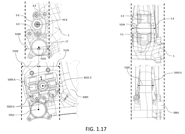
From a compliance perspective, in Fig. 1.17, Yeti show a rear view of the seat tube with both the current Switch Infinity system and the proposed suspension system. They claim that
5104 is horizontal distance of the linkage interface between swingarm body 2-E and link body 5-E. 5105 is horizontal distance of the linkage interface between swingarm body 5002-E and link body 5005-E. It is clear that 5104>5105. The wider interface as disclosed herein allows for a stiffer interface between swingarm body 2-E and link body 5-E which translates to a stiffer interface between swingarm body 2-E and the suspended body 1. This allows greater performance by improving the handling accuracy of the vehicle”.
In short, the wider profile of the proposed system would provide more stiffness, leading to better handling. Figure 1.17 is used in this article because it’s the same as the geometry in this article.
From a simplicy perspective, Yeti state:
The difference in embodiment 3 being suspended body 3001 is integrated into a single structure with link body 3003, link body 3004, and link body 3005. This eliminates all hardware and rotary/revolute bearings/ bushings/etc. in the 200 assembly of the above discussed first embodiment. As a result, it is possible to even further reduce the weight of the assembly while retaining similar kinematic behavior and optimizing manufacturability.
So, Yeti are doing this for lighter, easier to manufacture, pivot system. Yeti state that using these flex pivots provide a huge advanatage:
Flexural components 3003 and 3004 are integrated into suspended body 3001 and may be made from composite such as carbon fiber which has a high or infinite fatigue life ideal for the cyclic bending loads that will occur with these components.
For the cynics, Yeti are claiming that the use of the flex pivots may provide up to an infinite life-time.
What
In the first article, Yeti introduced a 6-bar suspension system, with a smaller 4-bar system, that is not concentric with a second pivot due to the solid swing arm. The result should be similar to the current Switch Infinity system with an inflection point and a reversal of the bottom pivot. The important distinction is that the linear migration path of the bottom pivot in the current Switch Infinity system is not the same as the non-linearity of this invention.
The special sauce with this part of the patent is that the smaller 4-bar system is integrated into the frame with flexible brackets holding the pivot in place. The flexible links are not bolted to the front triangle, they are one piece and hold a set of bearings.
The proposed method creates a linear migration path of the bottom pivot in the middle of the migration path and has a small amount of curvature at both ends of the migration path, at the beginning and end of travel. Yeti state that this development creates
…higher antisquat percentage…for pedaling efficiency in the beginning of the travel while the lower anti-squat percentage minimizes the anti-squat force where bump absorption takes precedence”.
How
We’ll start with some brief background. There are 3 different states of a Yeti bike; an extended state (E), an inflection state (I), and a compressed state (C). As with the Switch Infinity system, Yeti like to use an inflection state, where the bottom pivot of their suspension system changes direction. The extended state is a static, no-load state. The compressed state is fully hucked to flat state.
Next, let’s talk about important components. The table below shows links and pivots in the system that contribute to the new suspension system.

| Swingarm 2 (not shown) | Rear triangle – connected to PIVC 3045 and 3046 |
| Link 3003 | Bottom link to the bottom pivot attached to front triangle |
| Link 3004 | Top link to the bottom pivot attached to front triangle |
| Link 3005 | Middle link to the bottom pivot attached to swingarm |
| Link 3006 | Link body attached to swingarm and shock |
| “PIVC” 3040 | Bottom flex arm |
| “PIVC” 3041 | Top flex arm |
| PIVC 3042 | Front triangle and link 3006 pivot |
| “PIVC” 3043 | Bottom flex arm |
| “PIVC” 3044 | Top flex arm |
| PIVC 3045 | Pivot at Center of link 3005 |
| PIVC 3046 | Swingarm and link 3006 pivot |
| PIVC 3047 | Link 3006 and shock pivot |
Figure 1.1 (again, same as this article) shows the proposed suspension system in a fully extended position. The swingarm (component [30]02) is attached at PIVC [30]45 and PIVC [30]46. The upper pivot of the swing arm pivot is linked at PIVC [30]46, pivots around PIVC [30]42. The swingarm is also attached to a bottom pivot system. This bottom pivot system is the novelty of this invention. It’s important to remember that PIVC [30]45 is the bottom pivot that is connected to the swingarm and will be performing the up-down movement.

Figure 1.11A and 1.12 (samsies) shows two detailed views of the seat tube with the suspension in an extended state and a compressed state, without the swingarm. As the bike goes through its travel, the shock is compressed around PIVC [30]42. Again, the swingarm is pivoting about PIVC [30]45 and [30]46. Here’s where it gets tricky. There is binding in the system due to the swingarm being a solid piece and the lack of concentricity with the 2 pivots. This is solved (and was solved in the Switch Infinity) by using a movable bottom pivot (PIVC [30]45).

There is a concentric rotation of the shock link body 3006 around PIVC 3042. Consequently, because the rear swing arm has zero pivots, this rotation is not concentric around the pivot link body 3005, which is constrained by flex links 3003 and 3004. The Watts 4 bar system constrains a center moving point in such a way that the center moving point (PIVC 3045) moves in a nearly straight line, using two flex links (3003 and 3004). Different from the first article, in this case with integrated flex pivots, there is no explicit PIVC that the flex links rotate around. There are representative PIVC’s for these pivots, but that goes too far into the weeds. If you want to read about them, do a search for 3040 or 3043 in the patent.
Because this design uses the same Watts system as article 1, I’m using Figure 1.35 to show an example (possibly exaggerated) migration path of PIVC 45 (the same PIVC as 3045). As you can see, the ends of the migration path have a small amount of curvature. This curvature is the novelty of this migration path.

Figure 3.15 shows a side view of the bottom pivot movement as the bike goes through it’s travel. Again, note the E, I, and C as extended, inflection, and compressed states. As the bike goes into its travel, the swingarm PIVC 3045 travels upward to an inflection point then downward during a fully compressed state. Note the perceived extreme movement of the flex arms. The PIVC 3045 moves in, effectively, the exact same path as the example in article 1.

Well, that’s the geometry. Now let’s talk about how they’re implementing the concept in the real world.
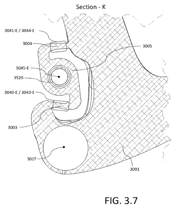
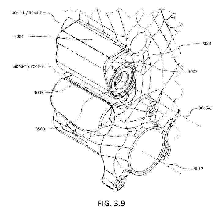
Aside from the typical shock linkage, there is a small device behind the seat tube, just above the bottom bracket. Figure 3.9 shows an isometric view of one of the proposed systems installed on a bike. Figure 3.7 shows a side cross-section view of the same system. As you can see, the configuration appears to be smaller and possibly simpler/lighter than the current Switch system and the flex links 3003 and 3004 are physically integrated into the front triangle. These links are then attached to link 3005. This is the Watts 4 bar system, but implemented in a very cool way. Whether it works or not, it’s still cool.
Another configuration of this system is shown in 3.18. This system uses two integrated flex links, but the bearing housing is bolted to the flex links rather than integrated. I would bet that this is probably what will be produced, as servicing will be cheaper and easier.

Separating the combined body into separate assembled components has several advantages. first, the parts may be composed of varying materials with varying material properties, each of which may be chose to optimize the properties such as weight, cost, stiffness, manufacturability, fatigue life, etc.
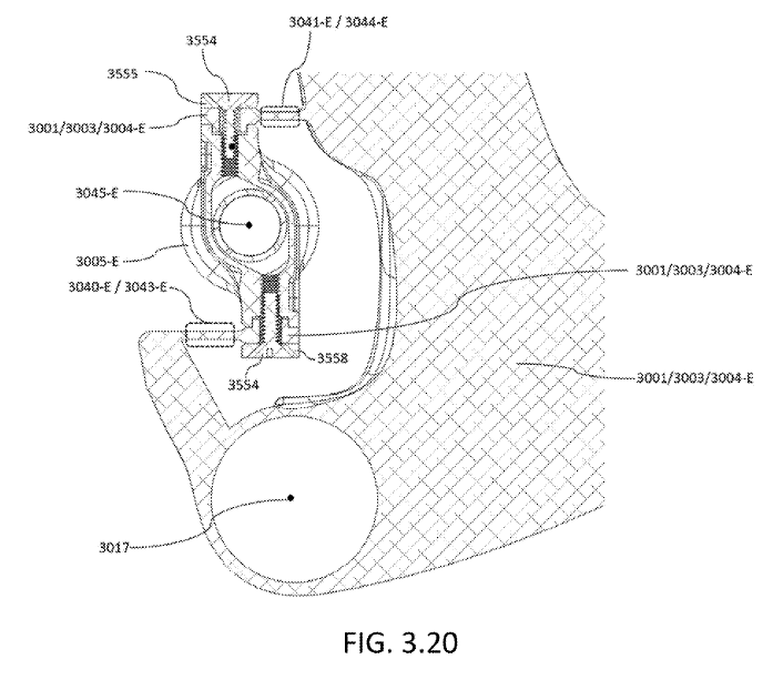
Figure 3.17 shows an exploded view of the same set up from figure 3.18. 3.20 is a cross section of this example.

When
Words by Mike Kazimer at Pinkbike:
When will we see this system released on a new bike? Well, according to Yeti, not any time soon – “We are constantly developing and exploring new ideas. However, not all R&D projects make it to production. We have several test mules of various suspension designs that we’ve been on for years. At the present, we are planned out through 2023 and this patent isn’t in our production line.” All the same, it’s interesting to get a glimpse at what’s being developed, and to examine the different elements that make up a new suspension system.
In the end, Yeti are really moving this Switch Infinity idea forward. In this particular example, they’ve really outdone themselves. I know there will be a lot of people unhappy about this, but not only is it pretty amazing what they’ve come up with, they’ve got a big set of balls to do it, too. I’m both extremely impressed with the idea and this patent document. It gets very deep into the background of the concept and is fairly clear as to what the design is. The combination of a 6-bar system, with a tiny 4-bar system, with flex pivots integrated into the frame is easily the wildest suspension concept I’ve seen. I’m sure others have some differing opinions, but this one is hard to beat.
So what do we think? Is this a viable design? Is Yeti reaching? Would you buy one? As far as I can tell, this may be used on the XC bikes. The combination of low servicing and super light weight design would be perfect for an XC bike. But lets not forget, if one of these flex pivots breaks, the front triangle is trash. You better buy new.
That may be a little dramatic. The reality is, is these guys and girls over at Yeti are much smarter than you or I and have probably thought this one out. I don’t think they’re unaware that this could be a problem and have probably done enough homework to justify it’s existence. If nothing else, it’s a show piece to show their superior manufacturing power. Or, it’s a recall waiting to happen. We’ll see. Either way, I absolutely love this out-of-the-box thinking.
If you think you see something wrong in this article, please email me. We can’t have misinformation out there. Even if you’re not 100% sure you’re right, I’d still like to hear from you.


Leave a Reply