In this article, we’ll be discussing a Integrated Active Valve Assembly by Fox, US publication 20210300140. The publication date is Sept 30th, 2021 and the filing date is March 25th, 2021. This patent is not granted.
Long article…
Brief Summary (tl;dr)
Fox are developing their own wireless and active suspension system. Yup, wireless. It’s pretty self-explanatory from a high level: sensors sense movement, the controller tells the valve what to do, the valve self-adjusts based on algorithms. The controller is attached to the back of a fork lower and is wired to the bottom of the active valve assembly. The valve is pretty cool, in that it’s not an on/off system. Rather, there’s a set of solenoids, fluid chambers, and pistons that control the spring, which controls a nipple in the valve. So, the nipple can be opened easily, or closed, or anything in between based on the fluid pressure. As a result, the damping rate is controllable and variable.
The weird part here is the communication and control of a rear shock using the front controller. It basically works like the EI system, where the rear shock has a time-delay based on the fork sensors and speed of the bike. So, it doesn’t actually react to the rear wheel, it’s just an extrapolation of the fork sensors.
Background
So, we’re all very aware of SRAM’s eventually-to-be-announced active suspension system. It’s been the second-worst kept secret behind the Yeti E-bike. The interesting thing about this new SRAM system is that it’s completely wireless, which seemed to be the main gripe with Fox’s Live Valve system. Lots of wires equal lots of maintenance and lots that can go wrong. So, it looks like Fox need to figure out a wireless system or they’ll get left behind.
Additionally, whoever wrote this application did a great job explaining technical terms, while including some awesome general information. This is better than I could explain, so I’m just going to copy some important lines for you to read to get your noodle going.
In the following discussion, the term “active”, as used when referring to a valve or shock assembly component, means adjustable, manipulatable, etc., during typical operation of the valve…. it will be understood that in some embodiments…
…an active valve may also be configured to automatically adjust its operation, and corresponding shock assembly damping characteristics, based upon, for example, operational information pertaining to the vehicle and/or the suspension with which the valve is used.
As is typically used in the suspension art, the term “active suspension” refers to a vehicle suspension which controls the vertical movement of the wheels relative to vehicle.
In a conventional “pure active suspension”, a motive source such as, for example, an actuator, is used to move (e.g. raise or lower) a wheel with respect to the vehicle. In a “semi-active suspension”, no motive force/ actuator is employed to adjust move (e.g. raise or lower) a wheel with respect to the vehicle. Rather, in a “semi-active suspension”, the characteristics of the suspension (e.g. the firmness of the suspension) are altered during typical use to accommodate conditions of the terrain and/or the vehicle.
Intro
This document is showing, what Fox are calling, an ‘integrated active valve assembly’. So, what does that even mean? It’s a self-contained active system that delivers a ‘stand-alone active valve assembly’. In short, this is a wireless and independent active system. The controller will adjust fluid paths in the valve to allow for different compression and rebound characteristics, based on what you (as the rider) choose to do.
Intended Novelty
Though this isn’t granted yet, it sounds like the explicit novelty is the fact that the controller is wired to the active shock assembly. I’m sure that’ll change as prosecution continues.
Why
Fox have a pretty vague statement on why they’re doing this:
…as with every collection of compromises, an advancement in one area almost always incurs a new problem or set of problems that require further advancement, analysis, and invention.
This is just saying they’re iterating, and this is the next step. Wireless everything.
What
FIG. 1C shows the entire system, including the rear shock controller. But, this document is primarily focused on the fork. 69 is the wireless switch, 35 is the front control module, 35b is the rear control module, and 288 is the all-important active shock assembly. The switch can be a phone, computer, watch, whatever has wireless and computing capabilities. Doesn’t really matter.

Assuming you’ve read my other articles about active systems, I don’t think I’m going to be able to tell you anything that you don’t already know. Sensor + Controller + Actuator = active. In this case, it’s semi-active.
…suspension controller module 35 will read bump input at the wheel, the pitch angle of the bicycle, telemetry attributes such as angle, orientation, velocity, acceleration, RPM, operating temperature, and the like. The suspension controller module 35 will use the sensor data to generate suspension adjustments for active shock assembly 288 via one or more of the active valves (e.g., active valve 450)… In so doing, the suspension controller module 35 can continually processes the sensor data and constantly provide adjustments to active valve 450 of active shock assembly 288 thereby adjusting the suspension stiffness of active shock assembly 288 for maximum efficiency and control.
This system is wireless and can communicate with your smartphone. This is to control the controller, that’s it.
…suspension controller module 35 can also communicate wired or wirelessly with other devices such as another controller, a mobile device, a computing system, and/or any other smart component(s) within a transmission range of suspension controller module 35.
The suspension controller will also be able to communicate with other controllers, as shown in FIG. 1C.
…suspension controller module 35 connectivity allows suspension controller module 35 to communicate with other controllers.
This is the part I’m a little confused about. Back in the day, Rockshox worked with Lapierre to create the EI shock. In short, this system had a controller on the fork and sensors to sense the bike’s speed. The fork controller would sense a bump and would send a wireless signal to the rear shock with a time-delay, based on the speed. As a result, the rear shock would adjust based on an assumed delay, rather than actively adjusting based on a bump of the rear wheel. I’m saying this because Fox are saying this is similar to how their system may work. I’m not so sure about this. I hope Fox have this figured out better than Rockshox (or Lapierre, whoever) did, because I don’t think it worked as well as it needed to. Let me know if you’ve used this. It was a great step to where we are today, but I think there’s a reason we don’t see it anymore.
…information from suspension controller module 35 at the front of the bike could be provided to rear suspension controller module 35b…. the information from the forward suspension controller module 35 can be used to provide the rear suspension controller module 35b with future-time information… the rear suspension controller module 35b will receive the information provided from the forward suspension controller module 35 a short time prior to the rear wheel reaching the location of the front wheel and encountering what the front wheel suspension had already encountered…. This would allow rear suspension controller module 35b to provide an active valve adjustment to the rear shock assembly 38 prior to the rear end encountering the upcoming terrain or suspension event.
Here’s something fucking stupid. Fox are saying that these controllers can communicate with another bike. Here’s the absolutely idiotic part; the first controller (first bike) can adjust the settings of a second controller (second bike) in a train.
…if two riders are riding two bikes within a communication range of the suspension controllers, one or more suspension controllers on each of the bicycles could be communicating wirelessly such that the suspension information from the lead bike is also provided to the follow bicycle(s)… In so doing, the suspension information from the lead vehicle can be used as future suspension information to the follow vehicle(s).
Why is the fucking fuck would I ever want the forward bike – that has nothing to do with my bike – determine my shock settings? I don’t hate a lot of things, but I hate this. I hope this never makes it to the actual system.
How
Here’s some detailed information on this system. Fox say the switch 69 will allow for three basic modes: open, lockout, and auto. Open would be your normal open damper system that doesn’t use any (or limited) bump sensing. So, a normal bike. The lockout mode would be what they’re calling a ‘sprint-type setting’, providing no bump sensing.

The auto mode is the special sauce. This mode would allow the suspension to operate in the ‘best’ configuration. The best configuration is determined by the algo-nerds that create the maps in the software. But, they also say the switch can be an on/off switch.
Such a “best” configuration could be based on terrain, rider, riding style, bike type, ride length, ride purpose, etc. For example, a “best” mode for a downhill mountain bike race would be a very active suspension configuration with a large range of motion, a “best” mode for a street race would be a firm suspension configuration with a very small range of motion, a “best” mode for a Sunday afternoon street ride would be a soft suspension configuration, etc.
FIG. 2A shows a perspective view of this new fork. It’s pretty simple. Controller 35 is wired to the damper 288 and the controller tells the damper what to do. That’s about it.
FIG. 2B shows the insidy parts of the fork. Controller 35 is to the right. This fork is just a basic assembly as doesn’t represent the actual detailed product. If you haven’t noticed, this is on the air-side. But, don’t look too much into that, because Fox also say this can be on the damper side. All you need to know is the controller is wired to the bottom of the piston, and controls valves in the fork.

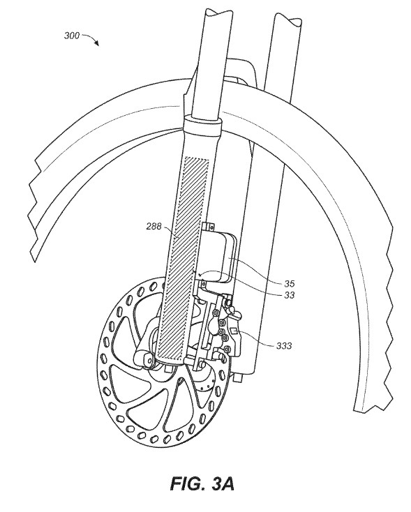
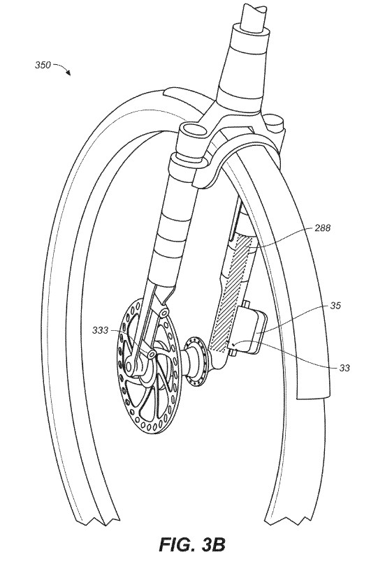
FIGs. 3A and 3B show more perspective views of the system. Nothing really important to note here, just interesting to see what it might look like.

So, here’s how the valve works. FIG. 4 shows the valve 450 and the fluid paths. This is just a diagram, and this should all be compartmentalized in the shock in the final product. The solenoids 775 (controlled by the switch) control the fluid chambers 751, 752, and 753 with a piston 765. These fluid chambers are connected to fluid chamber 707.
As the fluid chamber 707 is filled or released of fluid, the piston 705 applies pressure to the spring 715, which then applies pressure to the nipple 712. The more fluid in chamber 707, the more spring pressure to the nipple (like adding preload). The more spring pressure, the less fluid flow through the valve from inlet 702 to outlet 703. So, in the open position, there isn’t much spring pressure against the nipple and the fluid can flow more easily through the valve. In the closed position, there’s a lot of fluid pressure and the nipple is forced against the inlet not to allow fluid flow.
Screw 708 is a preload adjustor, in case you were wondering.

The horizontal red arrow is supposed to represent load to the spring.
It’s important to note that this system is variable and isn’t an open/closed system. Fox state this:
…the fluid contents of each cylinder can be used, individually, sequentially or simultaneously to move the piston a specific distance, thereby effecting the damping characteristics of the shock assembly in a relatively predetermined and precise way.
…the active valve 450, can be used to meter the working fluid flow (e.g., control the rate of working fluid flow) with/or without adjusting the flow rate through inlet orifice 702.
The result is a controllable damping rate.
Conclusion
So, we might be getting a wireless Live Valve. Interesting times we’re living in, right now. As I’ve said before in other articles, this type of thing should be super interesting to ride, but I’m still not a fan of it in racing (like we’ve been seeing in spy shots). I really like the variable valve. The current open/closed system works, but may not offer the freedom to design like a variable valve will.
But, I’m not convinced the delay-style system is correct, but wtf do I know. There’s a lot of variables to get that to work, and the explicit detachment from input -> output just doesn’t feel right. This is input -> delay -> output for the rear shock. Fox are smart, so it’ll probably work well.
Lastly, I’m going to go ahead and assume that this will be a consumer-only product and is designed to be a cheaper alternative to the current Live Valve system. I don’t think, for one second, that this will outperform the wired system. But it’ll be plenty for the normal trail rider to have fun and get better performance.


Leave a Reply