
Subscribe to continue reading
Subscribe to get access to the rest of this post and other subscriber-only content.
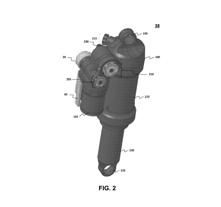
A new Live Valve variant from Fox
Subscribe to get access to the rest of this post and other subscriber-only content.
Note from the editor: These articles are for entertainment purposes only and should not be construed as legal advise. Please don’t be a dipshit and trust anything written by anyone on the internet, especially me. You should not act or refrain from acting based on any information provided through this website without seeking professional legal advice. If you need to link up with an attorney, shoot me a message and I’ll help you out.


5 responses to “Adjustable Shock Assembly Fox Factory”